Understanding Hydraulic System Components in Heavy Machinery
hydraulic cylinder pump valve hydraulic system maintenance excavator hydraulics
The hydraulic system is what transforms engine power into the precise, powerful movements that make heavy equipment useful. Understanding how it works helps you diagnose problems, make informed parts decisions, and keep your machines running efficiently.
How Hydraulic Systems Work
The basic principle is simple: a pump pressurizes hydraulic fluid, which flows through valves to cylinders and motors that perform work. The fluid then returns to the tank to be filtered and recirculated.
The key components in order of flow:
1. Hydraulic Tank (Reservoir)
Stores hydraulic fluid and allows air bubbles and contaminants to settle. Typical capacity: 150–400 liters for excavators. The tank also helps cool the fluid through its surface area.
2. Hydraulic Pump
Converts mechanical energy from the engine into hydraulic energy (flow and pressure). Types found in heavy equipment:
**Axial piston pumps** — Most common in excavators. Variable displacement allows the system to adjust flow on demand, improving efficiency.
**Gear pumps** — Simpler and cheaper, used for pilot circuits and smaller equipment.
**Vane pumps** — Used in some crane hydraulic systems for smooth operation.
The main pump is the most expensive hydraulic component, typically costing 8,000–15,000 SAR for excavators.
3. Control Valves
Direct fluid flow to the correct cylinder or motor. The main control valve on an excavator manages boom, arm, bucket, swing, and travel functions simultaneously.
**Spool valves** — Most common type, with precision-machined spools that slide to open and close ports
**Proportional valves** — Allow variable flow for precise speed control
**Pilot valves** — Small valves that control larger valves, operated by joystick inputs
4. Hydraulic Cylinders
Convert hydraulic pressure into linear force. An excavator typically has 6 main cylinders:
2 boom cylinders
1 arm cylinder
1 bucket cylinder
2 blade/dozer cylinders (if equipped)
Key specifications: bore diameter, rod diameter, and stroke length. These determine the force and distance the cylinder can push or pull.
5. Hydraulic Motors
Convert hydraulic pressure into rotational force. Used for:
**Swing motor** — Rotates the upper structure
**Travel motors** — Drive the tracks through the final drives
**Fan motor** — Drives the cooling fan (on some models)
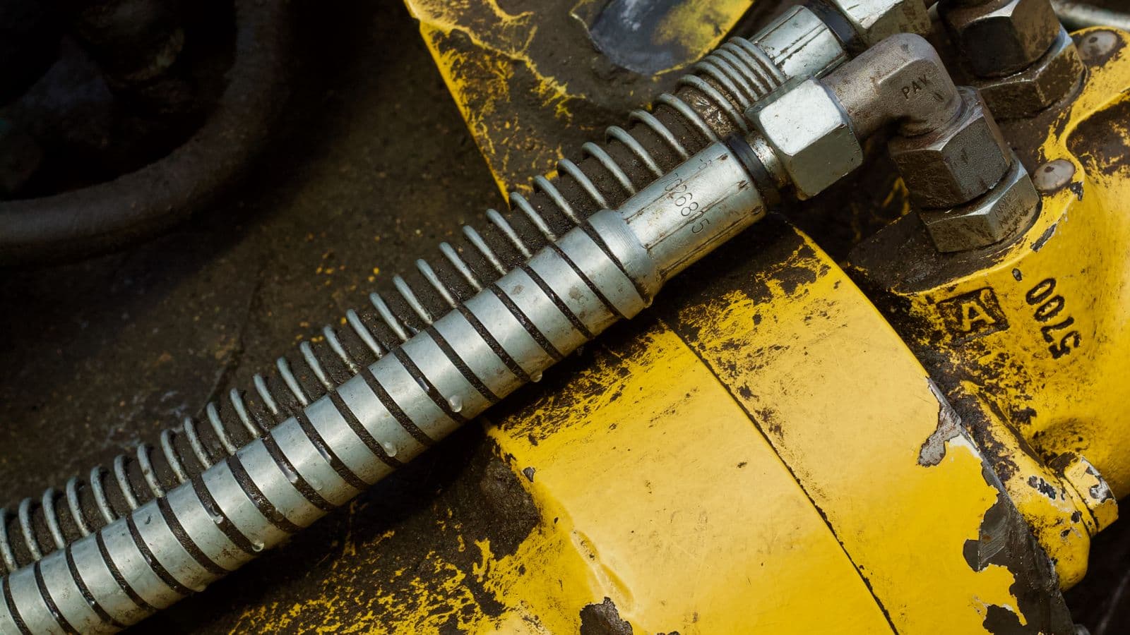
6. Hydraulic Lines
Hoses and steel pipes that carry fluid between components. Operating pressures typically range from 250–350 bar (3,600–5,000 PSI).
7. Filters
Remove contaminants to protect precision components:
**Suction strainer** — Coarse filter at pump inlet
**Return filter** — Main filter in the return line to tank
**Pilot filter** — Fine filter protecting the pilot circuit
Common Failure Modes
Pump Failure
**Symptoms**: Slow operation, high noise, overheating, loss of power